Thermoprotector with resistor (Caution to be observed when installing thermal links)
Cautions to be observed in installing EC
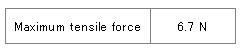
Do not apply tensile stress exceeding the force in Table 1to the lead wires for installation. The stress exceeding the force may cause malfunction of EC Series. Table 1
Do not pull, push, bend or twist the body and the lead wires. Do not pull or push the lead wires at an angle to the body.
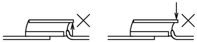
Do not apply any force toward the direction as shown in Figure 2 Figure 2 Caution to be paid for projection
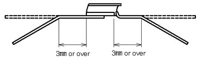
When bending the lead wire for installation, fix the part of the lead wire between the body and the lead wire section to be bent with a tool, and gently bend the lead wire section that is at least 3 mm away from the body. See Figure 3. Figure 3 Lead wire bending method
After EC Series is installed, do not apply excessive force that will damage its body or the lead wires, and ensure that the body and the lead wires should not be subjected to pull or push force.
Cautions to be observed for soldering and welding
Be sure to perform soldering condition confirmation test in advance, as the fuse part of EC may function depending on the conditions for soldering the lead wires.
The maximum soldering time for soldering one lead wire “B” and “C” of EC at the length of 10 mm from the body in a soldering bath (350℃) is about 3 seconds.
The maximum soldering time for soldering one lead wire “A” of EC at the length of 5 mm from the body in the solder bath (350℃) is about 5 seconds.
Be sure to leave it for minimum of 60 seconds for cooling before attempting the re-soldering or re-welding.
For staking or welding the lead wires, make sure to measure electric resistance over the joint part with a low ohm meter to check the jointing conditions.