Thermoprotector with resistor (Caution to be observed when designing for use of thermal links)
EC must have the lead wire “B” and “C” connected together under normal usage.
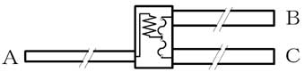
Install EC to make current flow “A to B” and “A to C” under abnormal condition so that fuse part shall operate by the heat from the resistor. Refer to the Figure 1. Figure 1 Circuit Diagram
Select positions and methods for installation properly to make EC function as it is originally designed. Make sure that their selections should be the best by testing in a number of end products as well as repeating the tests under both normal and abnormal conditions.
Rated current, rated voltage and maximum overload power are prescribed for EC. Use EC within those ratings. EC may not function if it is used over the ratings.
Since EC incorporates the fuse part, it can function by heat from over current as well as by ambient temperature rise. To avoid the EC’s function under normal condition, reduce load in accordance with the derating chart.
Provide appropriate insulation on EC and/or nearby electrical conductive materials in the following cases when selecting positions and methods for installation of EC at ambient temperature. ・Electrical conductive materials may cause short circuit between the lead wires. ・Electrical conductive materials may impair insulation or dielectric strength.
To ensure that EC functions properly, use it such that an electric power more than 3W and less than maximum overload power shall be applied to the resistor part in abnormal conditions. EC may function more quickly and surely with greater electric power supplied. However, if applied power exceeds the maximum overload power, the insulation resistance after functioning may be adversely affected, or EC may be damaged in some case. Do not apply the power exceeding maximum overload power to it in any case.
Install EC such that the temperature of EC increased by both its self-generating heat and by other components shall be 30℃less than functioning temperature, since EC generates a heat when current is applied.
If EC is to be installed by soldering, make sure that EC does not come off when solder melt by excessive heat caused by abnormal conditions. For example, hold lead wires of EC by inserting its lead wires into holes of PC Board, or hold EC onto PC Board using heat resistive Resin, heat resistive Tape and/or heat resistive Adhesive.
Do not install EC where it may be subjected to sever or continuous vibration.
Design equipments so that EC does not reach a temperature above its maximum temperature limit due to overshoot after functioning, etc. even in any abnormal conditions. Maximum temperature limit is the maximum temperature which does not cause re-closing of functioned fuse part for ten minutes without any load over the body and lead wires.
Ensure by testing prototypes and initial products in normal and abnormal conditions that EC functions as designed properly. Also, ensure by testing that EC does not function during the use of end products.