The Fusing Resistor BZ07 (Caution to be observed when designing)
The following instructions include explanations of cautions to be observed in designing equipment for installation of Fusing Resistor BZ07-○○○(hereinafter called BZ07). Read carefully before designing equipment, using BZ07.Inappropriate handling may cause a bad influence on the end product, such as disconnection and non-fusing-off. Please acknowledge that we take no resposibility for the problem caused by the inapproproate handling.
1. Cautions to be observed in designing for installation of BZ07.
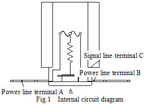
a) BZ07 must have the power line lead-terminal “A” and “B” connected together under normal usage. Refer to Fig.1.

b) Install BZ07 to make current flow “A to C” or “B to C” under abnormal condition so that the fuse part shall fuse off by the heat from the resistor part.
c) The data stated in our catalog indicates the characteristics and quality as a sole component.
When you use it, please install it into your end product and evaluate it under the normal and abnormal conditions carefully.
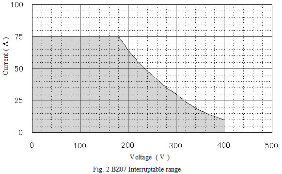
d) Rated current, rated voltage, interruptable range, operating temperature range, and interrupting wattage range are prescribed for BZ07. Use BZ07 within those ratings. If you use it beyond the interruptable range shown in Fig.2, the circuit may not be interrupted safely.

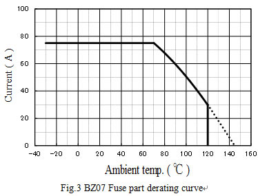
e) Since BZ07 generates Joule heat by current application, reduce the load in accordance with the derating chart to avoid the fusing-off under normal condition. Refer to Fig. 3.

f) If BZ07 is located close to other heat generating components, or other components and composition materials which do not favor heat influence, take an appropriate measure to avoid the thermal influence, such as installing heat insulating materials.
g) To ensure that BZ07 fuses off properly, it is necessary to design the end product properly so that an electric power within the interrupting wattage range (30W~62W) can be supplied. If an electric power out of the interrupting wattage range is supplied, the circuit may not be interrupted by causing calorie shortage and disconnection of resistor part.
h) When you choose the installing method of BZ07 and the heat dissipations of the circuit composing materials (for example bus bar) connected to BZ07 lead terminals are much different from each other, that may have a bad influence on the interrupting characteristic and not result in a safe interrupting. Design your circuit so that the circuit composing materials connected to BZ07 lead terminals cannot have much different heat dissipations each other.
i) When you choose the installing location and method of BZ07, and there is a possibility that the adjacent conductive material short the lead terminals of BZ07, or cause the insulation failure and the dielectric strength failure, make an appropriate insulation treatment on the conductive material.
j) Coating treatment, including insulating treatment to BZ07 shall not be recommended.
If you carry out coating treatment, investigate the heat resistance to Joule heat, the deterioration by a heat cycle, and the dielectric strength at the normal use, or after the fusing-off. Make a possibility decision on your own responsibility.
k)Do not install BZ07 where it may be subjected to sever or continuous vibration.
l) A permanent magnet is located inside the body of BZ07. If there is a component, or a circuit which does not favor the influence by the magnetic field, design your product so that it cannot be close to the magnet.
Application guidance
- ELCUT THERMAL LINKS INSTRUCTION MANUAL
- ELCUT THERMOPROTECTOR ETR INSTRUCTION MANUAL
- ELCUT THERMOPROTECTOR WITH RESISTOR EC INSTRUCTION MANUAL
- ELCUT THERMOPROTECTOR TR4L INSTRUCTION MANUAL
- ELCUT THERMOPROTECTOR TR6L INSTRUCTION MANUAL
- Thermal links/resistor assemblies (Caution)
- Thermal links/resistor assemblies (Caution to be observed when designing for use of thermal links)
- Thermal links/resistor assemblies (Caution to be observed when installing thermal links)
- Thermal links/resistor assemblies (Other caution)
- Thermoprotector with resistor (Caution to be observed when installing thermal links)
- Thermoprotector with resistor (Caution to be observed when designing for use of thermal links)
- Thermoprotector with resistor (Other caution)
- The Fusing Resistor BZ05 (Caution to be observed when designing)
- BZ05 (Caution to be observed when installing)
- BZ05 (Other caution)
- The Fusing Resistor BZ07 (Caution to be observed when designing)
- BZ07 (Caution to be observed when installing)
- BZ07 (Other caution)
- ELCUT Thermal links/resistor assemblies INSTRUCTION MANUAL
- Thermal links ( Caution)
- Thermal links ( Caution to be observed when designing for use of thermal links)
- Thermal links ( Caution to be observed when installing thermal links)
- Thermal links (Other caution)
